 Xelivor
Xelivor
Xelivor
Choosing the right pluggable optical transceiver can determine whether a network remains stable or becomes a source of repeated troubleshooting. The decision involves more than matching a module to a switch port. Engineers must examine transmission distance, fiber type, wavelength, data rate, connector design, and operating temperature. A module that looks suitable on paper may still perform poorly in a crowded rack or a dusty data center.
Real-world testing often reveals details that product sheets cannot fully explain. Check the switch’s compatibility list before ordering. Confirm whether the port supports SFP, SFP+, QSFP, or another form factor. Measure the actual fiber route, including patch panels and spare connections. A 10-kilometer rating may not solve problems caused by poor cable quality or excessive optical loss. Keep this in mind.
Reliable selection also requires attention to vendor quality and technical support. Look for documented test procedures, traceable product information, warranty terms, and clear monitoring support. Digital diagnostics can show temperature, voltage, transmit power, and receive power before a failure becomes visible. However, monitoring data still needs careful interpretation. Not every warning indicates a defective transceiver.
I have seen compatibility assumptions create unnecessary replacement costs. That mistake is easy to repeat. A practical evaluation should compare lifecycle cost, power consumption, network standards, and future upgrade plans. This guide explains how to assess these factors with professional judgment, while recognizing that no single pluggable optical transceiver fits every deployment. The best choice is the one that matches verified requirements, not the most impressive specification.
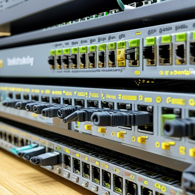
How to Choose the Right Pluggable Optical Transceiver?
Define Network Requirements Before Selecting a Pluggable Transceiver
Start with the network, not the transceiver catalog. Record the required data rate, link distance, fiber type, connector, and operating temperature. A short data-center link may need different specifications from a campus connection spanning several kilometers. Check whether the design uses single-mode or multimode fiber. This detail affects wavelength, reach, and optical power.
Review equipment compatibility carefully. Confirm the port standard, coding requirements, duplex method, and supported diagnostic functions. Calculate the optical power budget, including connector loss, splice loss, and aging margin. In field testing, small assumptions often create unstable links. Real networks rarely match the planning spreadsheet. Leave room for future traffic growth, but avoid paying for reach you will never use.
Tips: Build a simple requirement sheet before ordering. Include port speed, fiber type, distance, wavelength, temperature range, and power limits. Test one unit with the actual switch and cable assembly. Check alarms, temperature readings, and received optical power under normal load. Documentation should be clear and traceable. If a specification is uncertain, pause and verify it with the equipment manual or a qualified network engineer. A rushed selection can work today and fail after an upgrade.
| Network Requirement | Recommended Optical Type | Typical Data Rate | Wavelength | Fiber and Connector | Typical Reach | Key Selection Notes |
|---|---|---|---|---|---|---|
| Short links inside a data hall | Multimode short-reach transceiver | 10 Gb/s | 850 nm | OM3 or OM4 multimode fiber; duplex LC | Up to 300 m on OM3 or 400 m on OM4 for common 10G short-reach applications | Choose when low cost and high port density are more important than long distance. Verify the installed fiber grade and polarity. |
| High-speed server or switch uplinks over short multimode links | Parallel multimode transceiver | 40 Gb/s | 850 nm | OM3 or OM4 multimode fiber; MPO/MTP-style multifiber connector | Approximately 100 m on OM3 or 150 m on OM4 | Confirm the number of fiber lanes, connector keying, polarity method, and the switch port breakout requirements. |
| 10G access, aggregation, or campus links | Single-mode long-reach transceiver | 10 Gb/s | 1310 nm | Duplex single-mode fiber; duplex LC | Up to 10 km for common 10G long-reach specifications | Allow additional optical margin for patch panels, splices, connectors, and aging. Check whether the link is intended for single-mode infrastructure. |
| 25G server uplinks with moderate distance | 25G multimode or single-mode transceiver | 25 Gb/s | 850 nm for multimode; 1310 nm for single-mode | OM3/OM4 with duplex LC or single-mode fiber with duplex LC | Typically up to 70–100 m on multimode or up to 10 km on single-mode, depending on the specification | Match the transceiver type at both ends and confirm whether the equipment supports the required Ethernet rate and forward-error-correction mode. |
| 100G connections within a rack row or data hall | 100G short-reach parallel or duplex multimode transceiver | 100 Gb/s | 850 nm for parallel multimode; approximately 850 nm for duplex multimode designs | OM3 or OM4 multimode fiber; MPO/MTP-style connector or duplex LC | Commonly 70 m on OM3 or 100 m on OM4 for 100G short-reach parallel links | Use parallel optics when the cabling system supports multiple lanes. Check cable polarity, lane mapping, and whether breakout operation is required. |
| 100G single-mode links up to metropolitan distances | 100G single-mode wavelength-division transceiver | 100 Gb/s | Four wavelengths around the 1310 nm region | Duplex single-mode fiber; duplex LC | Approximately 2 km for common 100G four-wavelength designs or up to 10 km for extended-reach designs | Select according to the measured link loss and required distance. Confirm optical-budget compatibility between both ends. |
| 400G leaf-and-spine or data-center interconnect links | 400G parallel single-mode transceiver | 400 Gb/s | Approximately 1310 nm | Single-mode fiber; multifiber MPO/MTP-style connector | Up to approximately 500 m for common 400G parallel single-mode specifications | Verify host form factor, electrical lane configuration, connector type, breakout capability, and the required forward-error-correction support. |
| Low-latency or high-density deployments | Optical transceiver with the lowest suitable power class | Any supported Ethernet rate | Depends on the selected optical standard | Depends on the selected fiber architecture | Depends on the optical specification | Review maximum module power, switch cooling capacity, operating temperature, and total rack thermal load before purchase. |
| Long-distance single-mode infrastructure | Extended-reach or coherent pluggable transceiver | 100 Gb/s or higher | Commonly in the 1310 nm or C-band region, depending on the design | Single-mode fiber; duplex LC or a designated coherent optical connector | Tens to hundreds of kilometers, depending on modulation, amplification, dispersion, and line-system design | Do not select by distance alone. Validate dispersion, optical power, receiver sensitivity, amplification, channel spacing, and interoperability. |
: Identify single-mode or multimode fiber before choosing a module. Check the core type, connector, polarity, and patch-panel records. Physical fit proves little.
Measure the complete route, including patch cords, splice points, and connector losses. Compare total loss with transmitter power and receiver sensitivity. Distance ratings can mislead.
Yes. Confirm the port speed, optical standard, and signaling rate before ordering. A suitable wavelength cannot fix an incorrect data rate.
No. Fiber type, receiver sensitivity, transmitter power, and dispersion also affect performance. Short links may overload receivers with overly powerful long-reach optics.
Review insertion loss, return loss, dispersion tolerance, and bit error performance. Check the link budget against the actual installed route. Small losses accumulate.
No. Monitoring can show temperature, voltage, bias current, and optical power. Calibration differences may produce misleading comparisons. Measurements are useful, not absolute.
Check temperature, humidity, altitude, airflow, and power consumption ratings. A controlled-room module may struggle inside a warm, crowded cabinet. Heat changes outcomes.
Clean the connectors and test the complete pair with real traffic. Include startup, peak traffic, and temperature changes. A basic light check is insufficient. I have trusted quick tests before, and that assumption was weak.
Choosing the right pluggable optical transceiver begins with a clear understanding of your network requirements. Consider the transmission distance, data speed, fiber type, connector design, and operating wavelength needed for each link. It is also essential to confirm that the transceiver’s form factor matches the available port and that the equipment supports its specifications. Compatibility should be checked carefully to avoid installation problems, performance limitations, or unexpected network interruptions.
Beyond basic connectivity, compare optical power, receiver sensitivity, reach, standards compliance, and performance under the expected temperature and environmental conditions. Reliability is equally important, so review monitoring functions such as digital diagnostics, alarm reporting, and real-time temperature or power readings. Finally, evaluate total cost, replacement availability, energy use, and future scalability. A well-selected pluggable optical transceiver should meet current requirements while leaving sufficient flexibility for network upgrades and changing traffic demands.
