Xelivor
Xelivor
Xelivor
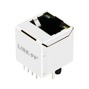
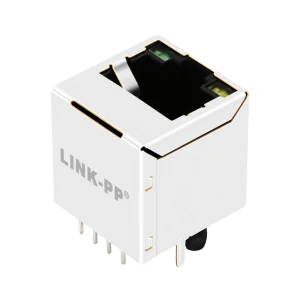
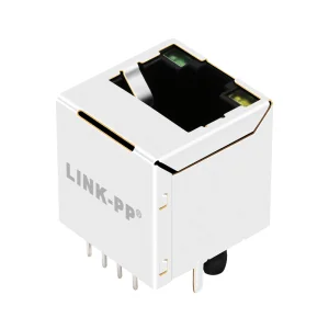
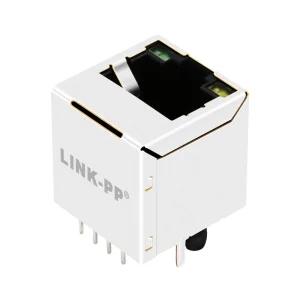
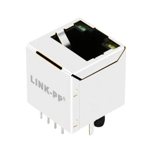
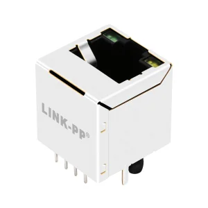
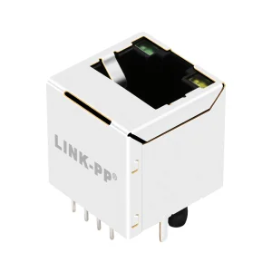
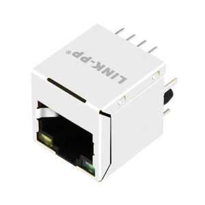
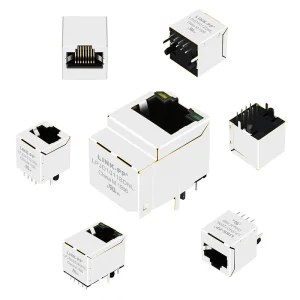
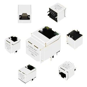
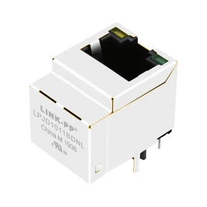
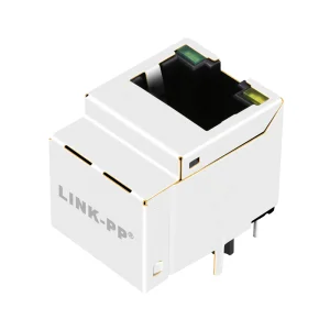
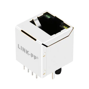
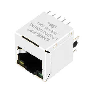
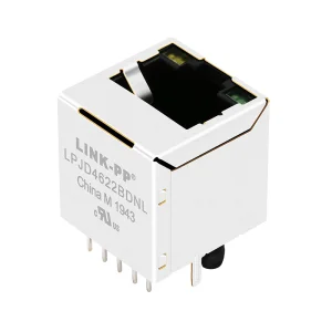
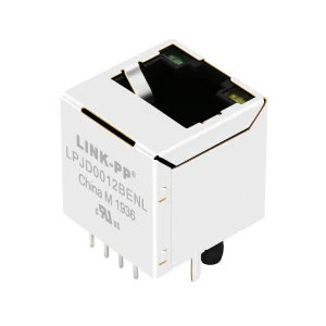
In modern high-speed PCB layouts, spatial economics represent one of the most significant engineering challenges. Traditionally, edge-mounted right-angle RJ45 connectors have served as the standard interface for Ethernet connectivity. However, as layout densities rise and the demand for space-efficient systems increases, the 180-degree vertical RJ45 female connector has emerged as a crucial component. By routing signals perpendicular to the PCB surface rather than parallel to it, engineers can reclaim valuable board-edge real estate.
From a signal integrity perspective, vertical layout geometries minimize the horizontal path length of traces leading to the physical layer transceiver (PHY) chip. This shortened routing configuration significantly dampens parasitic inductance and capacitive coupling, key contributors to Near-End Crosstalk (NEXT) and Far-End Crosstalk (FEXT) in high-frequency applications like Gigabit and Multi-Gigabit Ethernet. Crucially, mechanical stability must be designed in. Vertical insertion forces place straight downward stress on the board, requiring robust through-hole solder pins (plastic pegs or metal grounding tabs) to prevent trace delamination under high mating cycles.
Selecting the correct connector orientation dictates not only the mechanical design of the system enclosure but also the electronic performance limits of the hardware. The table below outlines the primary engineering differences between these two methodologies.
| Performance Metric | Vertical RJ45 (180-Degree / Top-Entry) | Right-Angle RJ45 (90-Degree / Side-Entry) |
|---|---|---|
| PCB Footprint Profile | Minimizes board surface area consumption; permits placement deep within internal layers. | Consumes board-edge boundaries; requires physical positioning at the board margin. |
| Mechanical Stress Vectors | Downward compression during patch cord insertion; requires secure mechanical anchoring. | Shear and rotational stress on solder pads; mitigated by chassis panel interference. |
| Thermal & Airflow Profile | Allows unobstructed vertical convective airflow adjacent to high-temperature components. | Can block system airflow vectors along the peripheral board boundaries. |
| PoE Heat Dissipation | Perpendicular mounting enables broader exposure to thermal sinks and natural heat dissipation. | Heat builds up in clustered horizontal rows, requiring extra thermal vias on the PCB. |
| High-Speed Trace Matching | Symmetrical vertical routing yields matched trace lengths directly into underlying PCB layers. | Asymmetrical internal pin lengths can lead to propagation delay differences. |
A modern vertical RJ45 connector is rarely just a plastic shell with pins. Higher data transfer speeds demand integrated electromagnetic compatibility (EMC) components. These units, known as Integrated Connector Modules (ICMs), house miniaturized toroidal transformers, common-mode chokes, and Bob Smith termination resistors directly inside the metal shield. This integration saves board space and shields sensitive signal components from ambient electromagnetic noise.
Constructed with nickel-plated copper alloys, our outer shields use integrated spring fingers to contact the chassis wall. This design shunts Electrostatic Discharge (ESD) safely to ground, keeping the internal signal channels noise-free.
Integrated Transient Voltage Suppression (TVS) diodes, featured in models like the 1840456-1, clamp overvoltage spikes from lightning surges and hot-plugging events, shielding vulnerable PHY transceivers from damage.
With configurations supporting IEEE 802.3af/at/bt specifications, our vertical PoE connectors carry up to 600mA of DC current per pair, keeping contact temperatures low and signal lines clean.
Vertical RJ45 jacks perform vital functions across diverse industries, satisfying localized performance mandates and solving distinct physical layout challenges.
In highly dense server systems and intelligent Power Distribution Units (PDUs) in North American and European hyperscale facilities, vertical RJ45 female connectors allow control boards to mount parallel to outer enclosures. This enables status ports to point outward without requiring bulky, angled ribbon cables.
In central Europe's smart manufacturing sectors, programmable logic controllers (PLCs) are often housed in thin, DIN-rail modules. Top-entry vertical connectors permit patch cables to enter directly from the top or bottom of the cabinet. This design keeps cable runs orderly and prevents damage from tight enclosure doors.
In dense urban IoT layouts and PoE LED driver assemblies, space is at a premium. Unshielded or waterproof vertical RJ45 jacks (such as the IP67 sealed models) fit into tight enclosures, providing dependable data and power connection points for smart infrastructure.
Quality is at the core of our operations. Xelivor Optoelectronics Co., Ltd. is a professional manufacturer of optical transceivers and high-performance interconnect solutions. Established in 2016, we have built a strong reputation for delivering reliable, high-performance optical and copper communication products worldwide.
With over 8 years of industry experience and 6 years of export experience, Xelivor has achieved annual export revenues exceeding USD 12 million. Our products are exported to customers across North America, Europe, Southeast Asia, the Middle East, and South America, supporting a wide range of networking applications from enterprise infrastructure to hyperscale data centers. Backed by a dedicated R&D team of 68 engineers, we continuously invest in innovation, launching more than 85 new products in the past year to meet the evolving demands of high-speed networks.
The company maintains long-term cooperation with more than 850 supply chain partners, enabling stable sourcing, efficient production, and rapid delivery capabilities. Our flexible manufacturing system supports OEM, ODM, private label, customized firmware, customized labeling, and packaging services to satisfy diverse customer requirements.
As communication protocols evolve, copper interconnect systems must keep pace. The technical roadmap for vertical RJ45 interfaces highlights three primary focus areas:
We are optimizing pin layouts and internal shield structures to handle Cat6a frequencies up to 500 MHz, allowing vertical connectors to deliver 10 Gbps Ethernet performance across copper lines.
We are upgrading our internal transformer packages to support Type 4 PoE++ power levels up to 90W-100W, using higher-grade copper alloys to limit internal heat generation.
We are designing hybrid industrial enclosures that combine standard RJ45 dimensions with Single-Pair Ethernet standards, facilitating smooth system upgrades across industrial sites.
Explore standard technical inquiries concerning the implementation, design, and deployment of vertical RJ45 jacks.
Vertical RJ45 connectors feature a tall physical profile, which can block hot air during convection reflow soldering. To ensure uniform heating, manufacturers use high-temperature liquid crystal polymer (LCP) plastics that tolerate peak temperatures of 260°C. To prevent cold solder joints, we recommend positioning vertical connectors away from tall shielding cans and utilizing appropriate stencil apertures to deposit sufficient solder paste.
Integrated magnetics (or MagJacks) consolidate the transformer, common-mode choke, and resistors into a single shielded package. This reduces overall PCB footprint requirements by up to 50% and isolates high-frequency noise from adjacent components. It also shortens the differential signal traces between the RJ45 port and the magnetic cores, enhancing electromagnetic compatibility (EMC).
Downward insertion force can stress PCB solder joints and lead to pad delamination. To address this, our vertical connectors incorporate thick plastic pegs or metal solder-in grounding shield tabs. These mechanical anchors distribute physical load directly to the board, shielding the delicate copper signal vias from stress.
Yes, specialized models like our HFJV1-2450-L12RL support PoE+ applications by utilizing contact pins rated for up to 600mA of DC current. Thermal management is critical; we use high-grade copper alloys to minimize electrical resistance and mitigate heat generation. Engineers should ensure adequate airflow and ground planes to help dissipate heat from the connector housing.
Shielded vertical RJ45 connectors are wrapped in a metal housing (often tin- or nickel-plated brass) that links directly to system ground, blocking EMI in high-frequency or industrial areas. Unshielded connectors (like the 87547-4111clf) lack this metal wrap, offering a cost-effective, space-saving solution for internal systems that are already shielded or operate at lower data rates.
To ensure long-term contact reliability, we specify selective gold plating (up to 50 micro-inches) over phosphor bronze contacts. The gold layer prevents surface oxidation, and the phosphor bronze substrate retains its physical spring force over time. This configuration is rated to maintain low contact resistance through at least 750 insertion and extraction cycles.
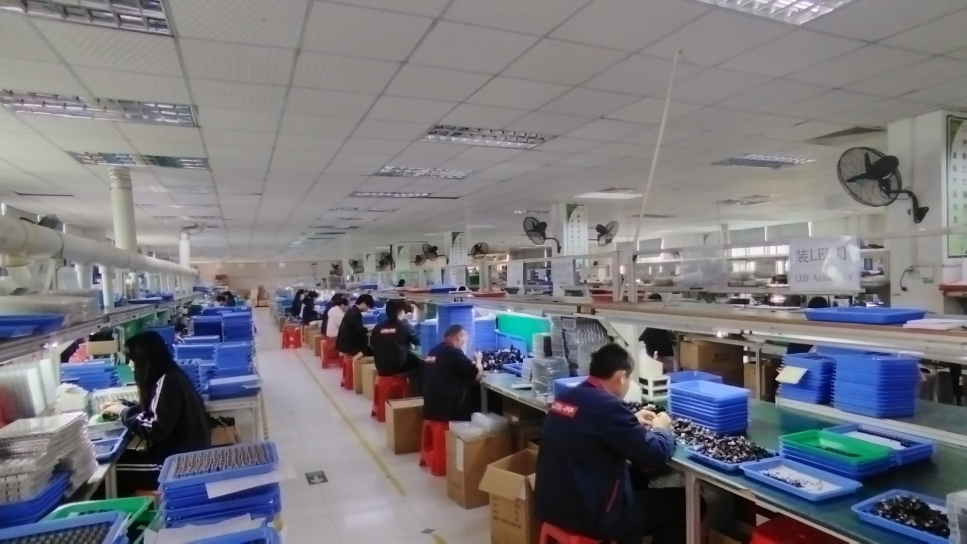
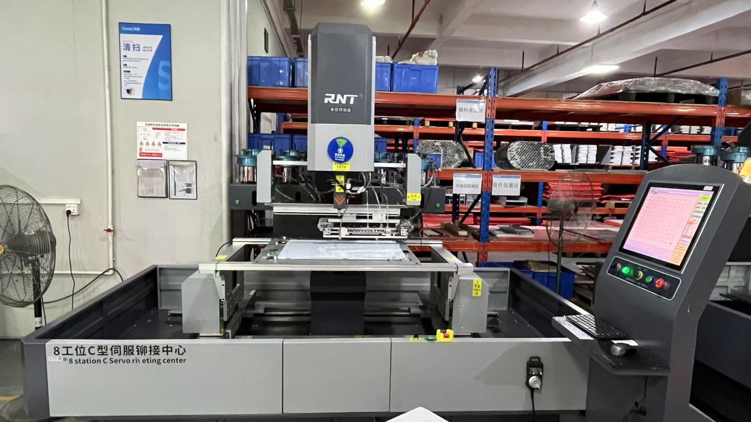
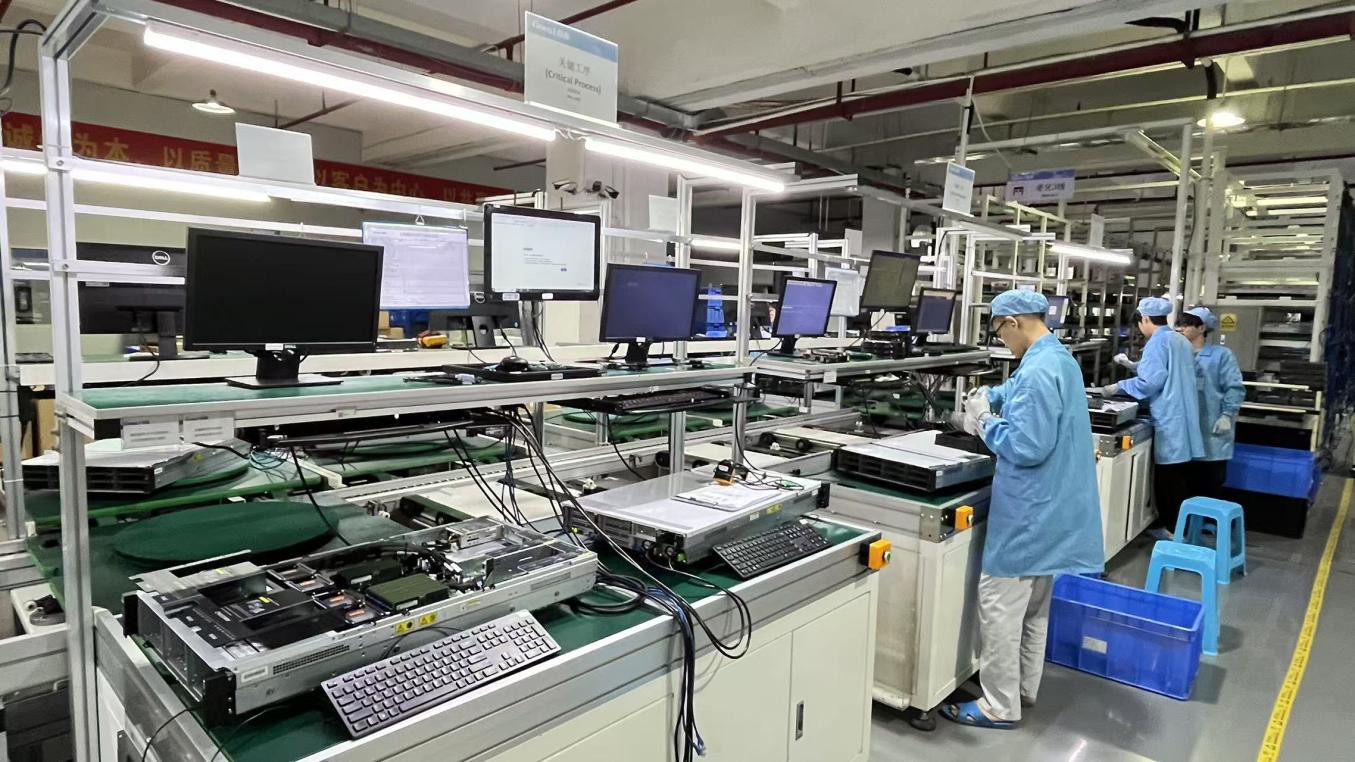
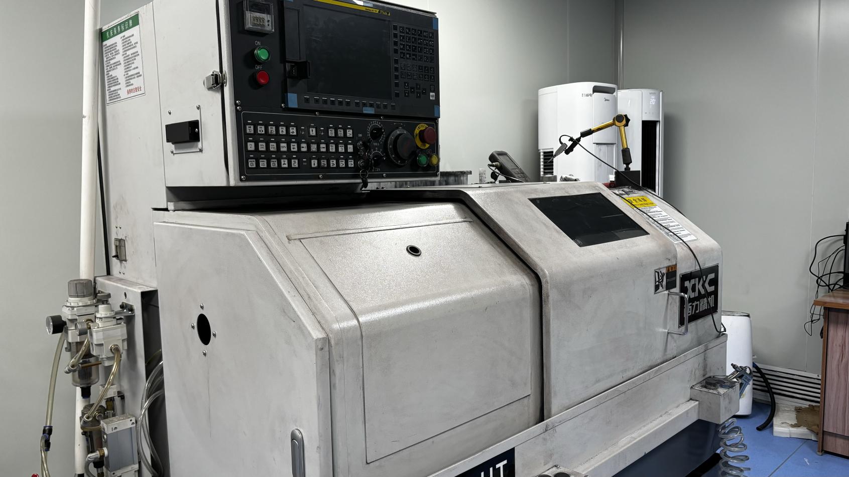
Our manufacturing centers use advanced assembly equipment, automatic testing machines, and cleanroom environments to maintain high production quality and stable supply volumes.