Choosing the right CWDM transceiver is becoming more important as networks carry heavier traffic across data centers, campuses, and metropolitan links. Cisco’s Annual Internet Report (2018–2023) projected global IP traffic would reach 396 exabytes per month by 2022. That growth increases pressure on fiber capacity, power budgets, and equipment reliability. A suitable module must match the real network, not only its advertised speed.
Start with distance, wavelength, and fiber type. A 10G CWDM transceiver for a 20-kilometer single-mode link may be unsuitable for a short, high-temperature cabinet. Check the exact CWDM wavelength, connector, optical budget, and operating temperature. Then verify compatibility with the switch, port coding, and management system. Digital diagnostics can reveal temperature, voltage, bias current, and received power before a link fails. Small details matter.
Reports from Dell’Oro Group and LightCounting continue to show strong demand for optical connectivity as data-center and transport networks expand. However, market growth does not make every transceiver dependable. A lower price can hide weaker monitoring, limited vendor support, or unstable interoperability. That is a useful warning. Review test records, warranty terms, qualification standards, and supplier experience. If possible, test the module with the actual switch, fiber route, and patch panel. A clean datasheet is not proof of field performance. Careful selection balances capacity, reach, temperature, power consumption, serviceability, and total ownership cost. The best CWDM transceiver is the one that remains stable after installation, not merely the one that looks impressive during procurement.
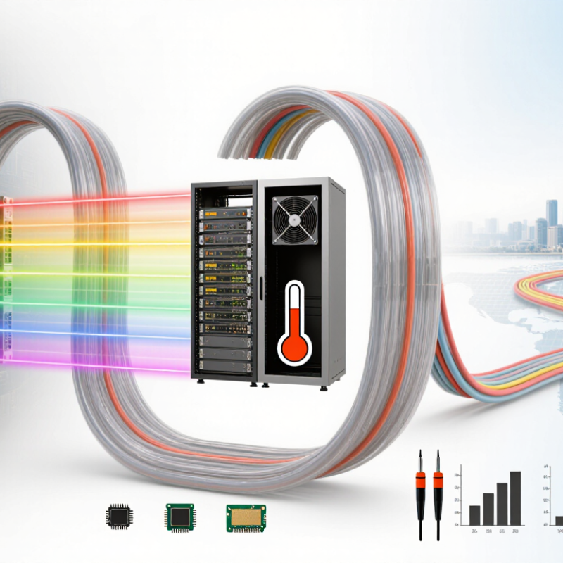
Define the CWDM Grid: ITU-T G.694.2 Uses 20-nm Channel Spacing
Choosing the right CWDM transceiver starts with the wavelength grid. ITU-T G.694.2 defines CWDM channels with nominal 20-nm spacing. Typical center wavelengths run from 1271 nm to 1611 nm, depending on the selected channel plan. The spacing is not the same as the optical bandwidth. It identifies where each channel operates. Check the transceiver label, equipment specification, and multiplexer port before ordering.
A practical match requires more than a wavelength number. Confirm the transmission rate, module form factor, connector type, fiber type, and required distance. Then compare the transceiver’s transmit power and receiver sensitivity with the complete link budget. Include connector loss, splice loss, multiplexer loss, and aging margin. A short cable can still produce problems when several passive components are installed. The 20-nm spacing offers useful tolerance, but it does not correct poor power planning.
One detail is easy to miss. Some systems use older wavelength labels, such as 1270 nm instead of 1271 nm. Verify the actual specification, not only the label printed on a package. Deployment checks should also include temperature range and digital monitoring support. A neat spreadsheet is not enough. Real installations may contain mixed patch cords, extra adapters, or undocumented repairs. Rechecking the optical path feels repetitive, yet it often exposes the small mismatch that causes intermittent alarms.
Match Transceiver Speed to 1G, 10G, 25G, or 100GbE Standards
Choosing a CWDM transceiver starts with the host port, not the wavelength label. Start with the port. A 1GbE switch usually requires an SFP module, while 10GbE commonly uses SFP+. For 25GbE, select an SFP28 module with the correct electrical lane rate. These formats are not automatically interchangeable, even when their wavelengths appear identical. IEEE 802.3 specifications define different signaling requirements for each Ethernet generation.
Match the optical module to the actual network standard. The Ethernet Alliance 2024 Ethernet Roadmap identifies 25GbE and 100GbE as important data-center deployment speeds. For 100GbE, a CWDM4 transceiver typically combines four optical wavelengths, each carrying about 25Gb/s, across up to 2 kilometers. That figure comes from the CWDM4 Multi-Source Agreement, not from a generic “100G” label. Check the standard carefully.
Distance matters too. A 1G link across a short campus route may need only a basic CWDM optic, while a 10G or 25G uplink may require tighter power and receiver specifications. I have seen installations fail because engineers matched speed but ignored dispersion, connector loss, or fiber type. It looked correct on paper. It was not. Verify single-mode fiber, channel spacing, DOM support, and switch compatibility before ordering. A few minutes with the interface datasheet can prevent an expensive field replacement.
Calculate Reach from Fiber Loss: G.652.D Attenuation up to 0.4 dB/km
How to Choose the Right CWDM Transceiver?
Calculate Reach from Fiber Loss: G.652.D Attenuation up to 0.4 dB/km
Choosing a CWDM transceiver starts with the optical link budget, not the advertised distance. For G.652.D fiber, use up to 0.4 dB/km as a conservative attenuation value. This figure can vary with wavelength, temperature, and installation quality. Measure the actual route when possible. Assumptions can mislead.
Subtract connector loss, splice loss, and engineering margin from the transceiver’s available power budget. Then divide the remaining budget by 0.4 dB/km. For example, an 8 dB budget may include 1.5 dB for connectors and splices, plus a 2 dB safety margin. The usable fiber budget becomes 4.5 dB. That supports approximately 11.25 km under the worst-case calculation.
Do not select an 11 km module for an 11 km route. A practical choice should leave room for aging, repairs, dirty connectors, and measurement errors. Ten kilometers may be safer. Check both transmitter output and receiver sensitivity in the datasheet. Verify the exact CWDM wavelength, because attenuation is not identical across the full wavelength range. Also confirm fiber type, connector condition, and power-monitoring results during commissioning. My early estimates often ignored small passive losses. They were too optimistic. A written loss table makes the decision more reliable.
How to Choose the Right CWDM Transceiver? - Calculate Reach from Fiber Loss: G.652.D Attenuation up to 0.4 dB/km
Planning formula:
Total link loss = Fiber attenuation × Distance + Connector loss + Splice loss.
Reach estimate:
Maximum fiber distance = (Transceiver optical budget − Fixed link loss) ÷ 0.4 dB/km.
The 0.4 dB/km value is used as a conservative planning coefficient for G.652.D fiber. Actual attenuation depends on wavelength, installation quality, temperature, bends, and the specific fiber cable.
1. CWDM Transceiver Optical-Budget Selection
| Optical Budget |
Typical Link Profile |
Fixed Loss Allowance |
Available Fiber Loss |
Maximum Calculated Reach |
Conservative Design Reach |
Selection Guidance |
| 5 dB |
Short campus or data-center link |
2.4 dB |
2.6 dB |
6.5 km |
Up to 5 km |
Use only when measured loss is low and the route is short. |
| 10 dB |
Metro or building-to-building link |
2.4 dB |
7.6 dB |
19 km |
Up to 15 km |
Suitable for moderate-distance links after loss verification. |
| 15 dB |
Extended metro or regional access link |
2.4 dB |
12.6 dB |
31.5 km |
Up to 25 km |
Provides additional margin for aging, repairs, and route uncertainty. |
| 20 dB |
Long regional link |
2.4 dB |
17.6 dB |
44 km |
Up to 35 km |
Choose only after confirming receiver overload limits and measured path loss. |
2. Fixed Link-Loss Assumptions Used in the Calculation
| Link Component |
Quantity |
Planning Loss per Item |
Subtotal |
Planning Note |
| Optical connectors |
2 |
0.5 dB |
1.0 dB |
Represents one connector pair at each end of the link. |
| Fusion splices |
4 |
0.1 dB |
0.4 dB |
Use the measured splice loss when available. |
| Engineering allowance |
1 |
1.0 dB |
1.0 dB |
Covers aging, maintenance activity, small repairs, and measurement uncertainty. |
| Total fixed loss allowance |
— |
— |
2.4 dB |
Applied to each reach estimate in the first table. |
3. Nominal CWDM Wavelength Grid and Fiber-Loss Planning
| Nominal Wavelength |
Channel Spacing |
Fiber Type |
Planning Attenuation |
Important Design Consideration |
| 1270 nm |
20 nm |
G.652.D single-mode fiber |
Up to 0.4 dB/km for planning |
Verify the transceiver operating range and cable attenuation specification. |
| 1290 nm |
20 nm |
G.652.D single-mode fiber |
Up to 0.4 dB/km for planning |
Confirm wavelength compatibility at both ends of the link. |
| 1310 nm |
20 nm |
G.652.D single-mode fiber |
Up to 0.4 dB/km for planning |
Often used as a reference region for standard single-mode fiber testing. |
| 1330–1490 nm |
20 nm |
G.652.D single-mode fiber |
Up to 0.4 dB/km for planning |
Check the fiber water-peak specification and the module's optical power budget. |
| 1510–1610 nm |
20 nm |
G.652.D single-mode fiber |
Up to 0.4 dB/km for planning |
Check bend sensitivity, connector reflectance, and actual attenuation at the selected wavelength. |
Example: For a 25 km route, fiber loss is 25 × 0.4 = 10 dB. Adding 2.4 dB of fixed loss gives an estimated total link loss of 12.4 dB. A transceiver with a 15 dB optical budget provides approximately 2.6 dB of remaining margin.
Verify Compatibility with ITU-T G.695 and MSA Interoperability Requirements
How to Choose the Right CWDM Transceiver?
CWDM selection begins with standards, not price. ITU-T G.695 defines optical interfaces for coarse wavelength division multiplexing systems. Check the channel plan, wavelength tolerance, launch power, receiver sensitivity, and maximum link loss. A transceiver may show “CWDM compatible,” yet fail across a long fiber span. That label is not enough.
Cisco’s Annual Internet Report estimated 5.3 billion internet users and 29.3 billion networked devices by 2023. This growth increases pressure on existing fiber infrastructure. Therefore, verify each module against the intended capacity and distance. Confirm its center wavelength matches the passive multiplexer. Then compare optical power budgets, connector types, operating temperature, and digital diagnostics.
MSA interoperability also matters. The host switch, transceiver, and monitoring system should share the same form factor, electrical signaling, management commands, and alarm behavior. In practice, small firmware differences can still cause surprises. I have seen links pass laboratory tests but behave poorly after temperature changes.
Tips: Request a full compliance sheet, not a marketing page. Ask for G.695 references and applicable MSA documents. Test both ends with the same fiber type and patch-panel configuration. Record receive power before deployment. A simple spreadsheet helps expose mismatched wavelengths and margins. Do not assume identical part numbers guarantee identical performance; revisions happen.
Conclusion
Choosing the right CWDM transceiver starts with understanding the CWDM grid defined by ITU-T G.694.2, which uses 20-nm channel spacing across the optical spectrum. Select a transceiver that matches your network speed, whether 1G, 10G, 25G, or 100GbE, and confirm that its wavelength fits the planned channels. Reach should be calculated from total fiber loss, including distance, connectors, splices, and system margins. For G.652.D fiber, attenuation may reach up to 0.4 dB/km, so sufficient optical power is essential for reliable transmission.
Before deployment, check the transceiver’s transmit and receive power, operating temperature range, and SFF-8472 diagnostic support for monitoring performance. It is also important to verify compliance with ITU-T G.695 and relevant MSA interoperability requirements. A careful review of these factors helps ensure stable communication, predictable reach, easier maintenance, and compatibility with the existing CWDM infrastructure.
 Xelivor
